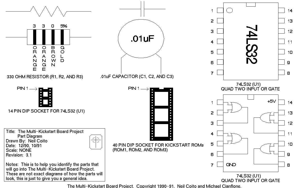
ocr: - 1 14 2 13 3 3 0 5% 3 12 .01uF 4 11 OBG - R - R . O 5 35 10 A A - O - L N N a - N W D 6 2 E E 7 8 330 OHM RESISTOR (R1, R2, AND R3) .01uF CAPACITOR (C1, C2, AND C3) 74LS32 (U1) PIN 1 PIN1 QUAD TWO INPUT OR GATE 1 +5V 14 14PIN DIP SOCKET FOR74LS32 (U1) 2 13 3 12 Title: The Multi-Kickstart Board Project 4 11 Part Diagram A Drawn By: Neil Coito - Date: 12/90, 10/91 40 PIN DIP SOCKET FOR KICKSTART ROMS 5 10 Scale: NONE (ROM1, ROM2, AND ROM3) Revision: 3.1 6 Notes: This is to help youi identify the parts that 7 GND 8 will go into The Multi-Kickstart Board Project. These this are is not just to exa ...